Timex Sinclair 1000 keyboard Serial Mod
I recently dug out my old Timex. Unfortunately the keyboard was dying. A couple of keys were dead. It turns out the keyboard uses a mylar ribbon connector, which dries out over time and cracks. I managed to rig something up to fix it. It did work, but a week later it was dead again.It turns out that finding replacement membrane keyboards is quite difficult.
So, I developed this single sided board which uses a BASIC Stamp microcontroller as a rs232 to Timex Keyboard Interface (TKI).
Now I can connect my Timex to the serial port of any computer running terminal software (plenty of freeware exist). I can now use my Mac or PC keyboard to type on my Timex.
The parts list is pretty simple:
| QTY | ITEM |
| 1 | BASIC Stamp BS2 |
| 14 | NPN Transistors |
| 14 | 10k resistors |
| 2 | .1uF capacitors* |
| 1 | DB9 female connector |
| *only needed to send Basic program to BS2. If you already own the project board, you don't need these. | |
Besides soldering the TKI to the Timex's keyboard lines, there was no other modification made to the Timex's circuit board. You could even install this to a perfectly working Timex and have both the real keyboard and the KTI working at the same time.
There was some free space on the board, so I also added a composite video output. You can see the schematic for that HERE. Just add 1 more NPN transistor, a 100Ohm resistor, and a female RCA jack to the list above
|
Here's all the files: |
|
| TKI-Schematic.gif | TKI Schematic |
| TKI-etch-rev.gif | PCB - etch side (reversed) (blown-up 4x) |
| TKI-parts.gif | PCB - parts side (blown-up 4x) |
| TKI.bs2 | BS2 Basic Source code |
| TKI.txt | BS2 Basic Source code (.txt version) |
How It Works
The Timex has 40 keys. It divides these keys in a 8 x 5 matrix, so the keyboard has 13 (8+5) wires to it. To make a key press, just connect 1 of the 8 rows to 1 of the 5 columns.
All the TKI does is decide which of the 8 rows should connect to which of the 5 columns.
All the keyboard lines are connected to a transistor (rows to the emmiters, columns to the collectors). All of the bases of the transistors are connected to the BS2. Then, all the remaining leads are all tied together to form a Bus. Now, if the BS2 sets a base HI, it allows the transistor to pass the current to the Bus.
The only exception is the SHIFT key. That's the only key that every gets pressed at the same time as another key. I had to add another transistor just for this (The transistor connected to P14).
The Source Code
All the source code does is read in a byte of ascii data, then decide what pins to set HI. I also added in a Macro feature, where a certain ascii code will execute a series of keypresses. Currently, sending a right-square-bracket ], will type LOAD "".
Unfortunately, the BS2 is a little slow when reading serial data, so if you type too fast, it may miss data. But, the Timex is slow, too, so it kind of evens out. You may get better results playing around with the Timeout delay in the SERIN command.
Some Timex keys don't exist in ascii, so here's the conversion I came up with:
| a-z, 0-9, ENTER, SPACE | No Conversion |
| A-Z | Like pressing SHIFT and a-z |
| !@#$%^&*() | Like pressing SHIFT and 0-9 |
| Backspace | SHIFT - 0 |
| \ , | (backslash, pipe) | SHIFT-ENTER |
| _ (underscore) | SHIFT-SPACE |
| " | SHIFT-P |
| If there was any punctuation that didn't interfere with anything else, I tried to implement it, like... | |
| ; | SHIFT-X |
| < | SHIFT-N |
| But, sometimes the conversion would mess things up. For instance the * asterisk. To get the asterisk, you need to type a capital B. The ascii for the asterisk is used as SHIFT-8. | |
DIsclaimer: I by no means consider myself a hardware expert, or even amateur. I 'proudly' consider myself a hardware HACK. The cicuit may not be efficient, and may blow up over time, I don't know. But, I do know that it does work. I have built and tested it myself, and it works for me.
Here's some pics during constuction:
 |
 |
|
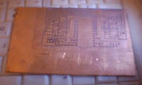
The 'raw' pc board with schematic.
|
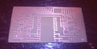
The board etched and cut.
|
 |
 |
|
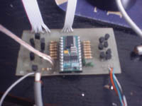
All parts soldered and wired.
|
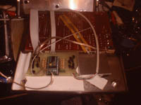
The board inside the Timex, all soldered in and connected.
|
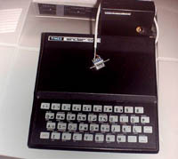 |
The finished product. I probably will eventually mount the connectors to the case (I didn't feel like cutting the case at the time). So, the wires just run from expansion port in the back. There is just enough room for the wires plus the 16k ram. |
Any questions or comments, just email me here.